GDT Drawing Callout. Cannot open file 1.
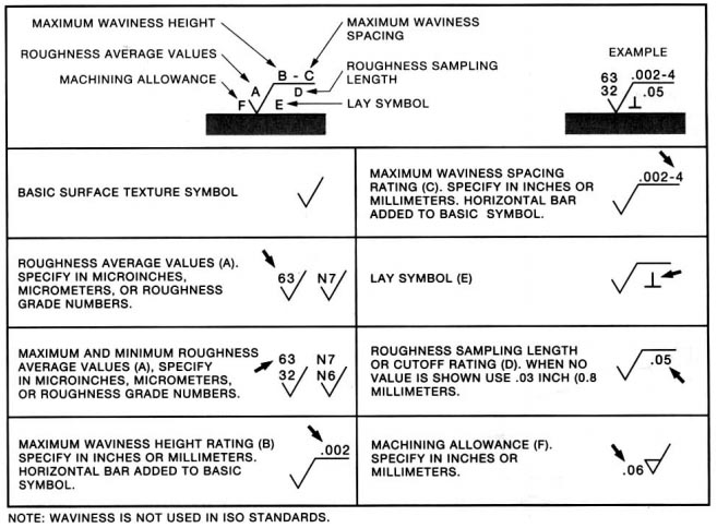
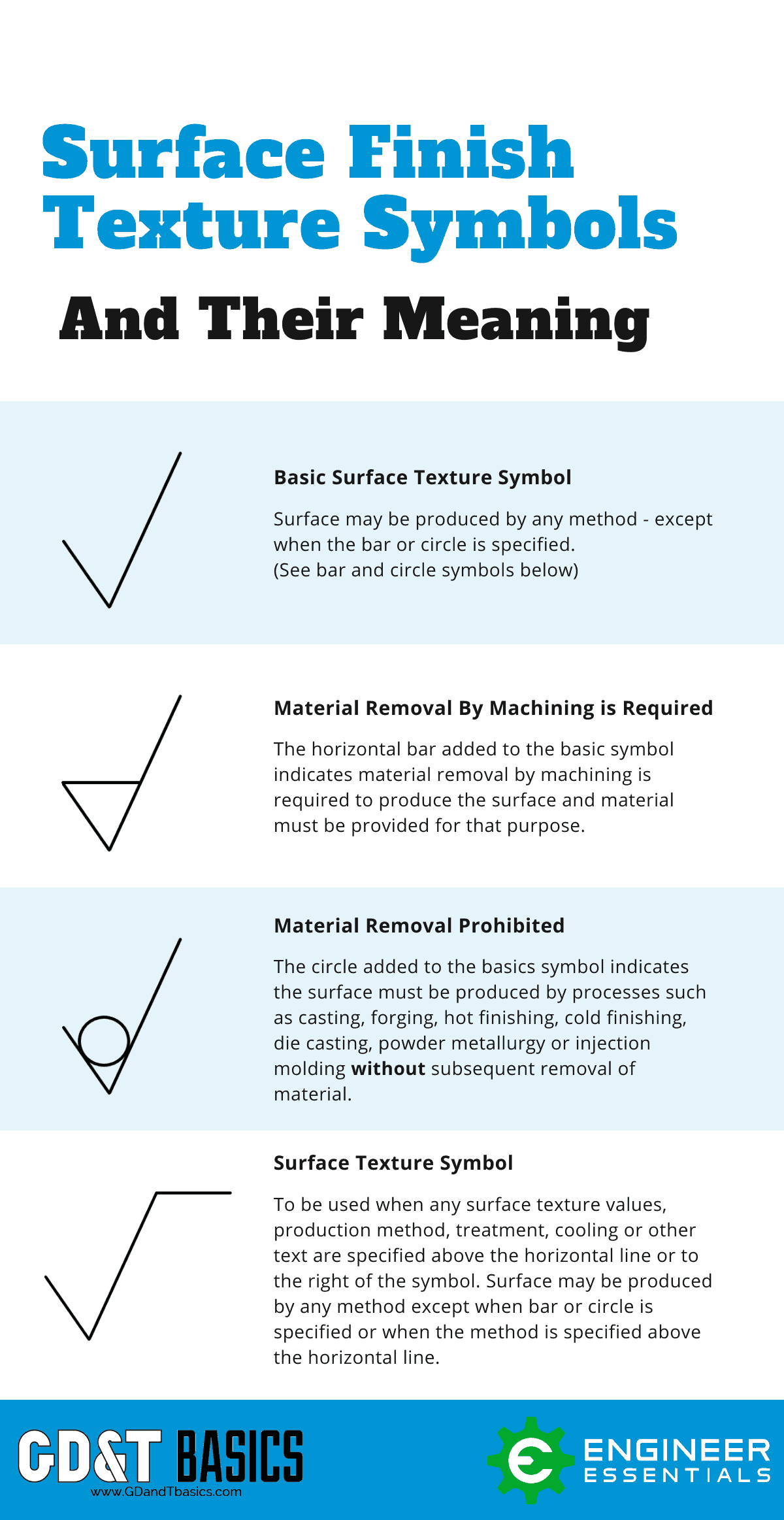
Complete Surface Finish Chart Symbols Roughness Conversion Tables
It can reference a 2D line referenced to another element but more commonly it relates the orientation of one surface plane parallel to another datum plane in a 3-Dimensional tolerance zone.
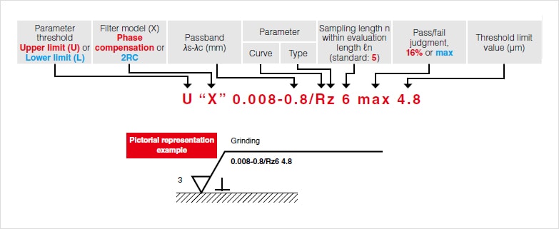
. If only one surface requires a specific surface roughness finish then it should be annotated on the drawing and not on the notes. I have some text Id to have as a color other than black. Cant edit element 1.
The standard surface roughness of the parts machined on Hubs is Ra 32 μm 125 μinch. I tried changing it in Edit Type in the color parameter under Graphics I changed it to a shade of blue but it does not affect the text color. CFD Not Responding 1.
Finishes to a surface roughness of Ra 16 μm 64 μinch and 08 μm 32 μinch are also available. Any help would be appreciated. I am using Revit 21016.
Parallelism is a fairly common symbol that describes a parallel orientation of one referenced feature to a datum surface or line.
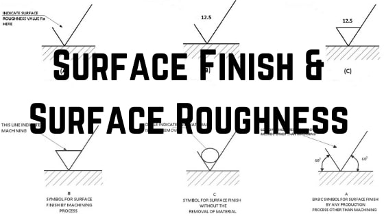
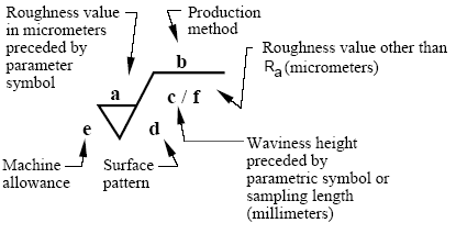
Surface Finish Surface Roughness It S Indications Symbols

Surface Roughness Symbol In Drawings Mechanical Engineering General Discussion Eng Tips

Understanding Surface Roughness Symbols Introduction To Roughness Keyence America
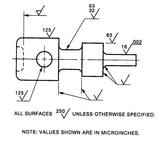
Complete Surface Finish Chart Symbols Roughness Conversion Tables
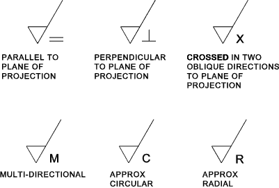
Dimensions Surface Finish Roy Mech

0 comments
Post a Comment